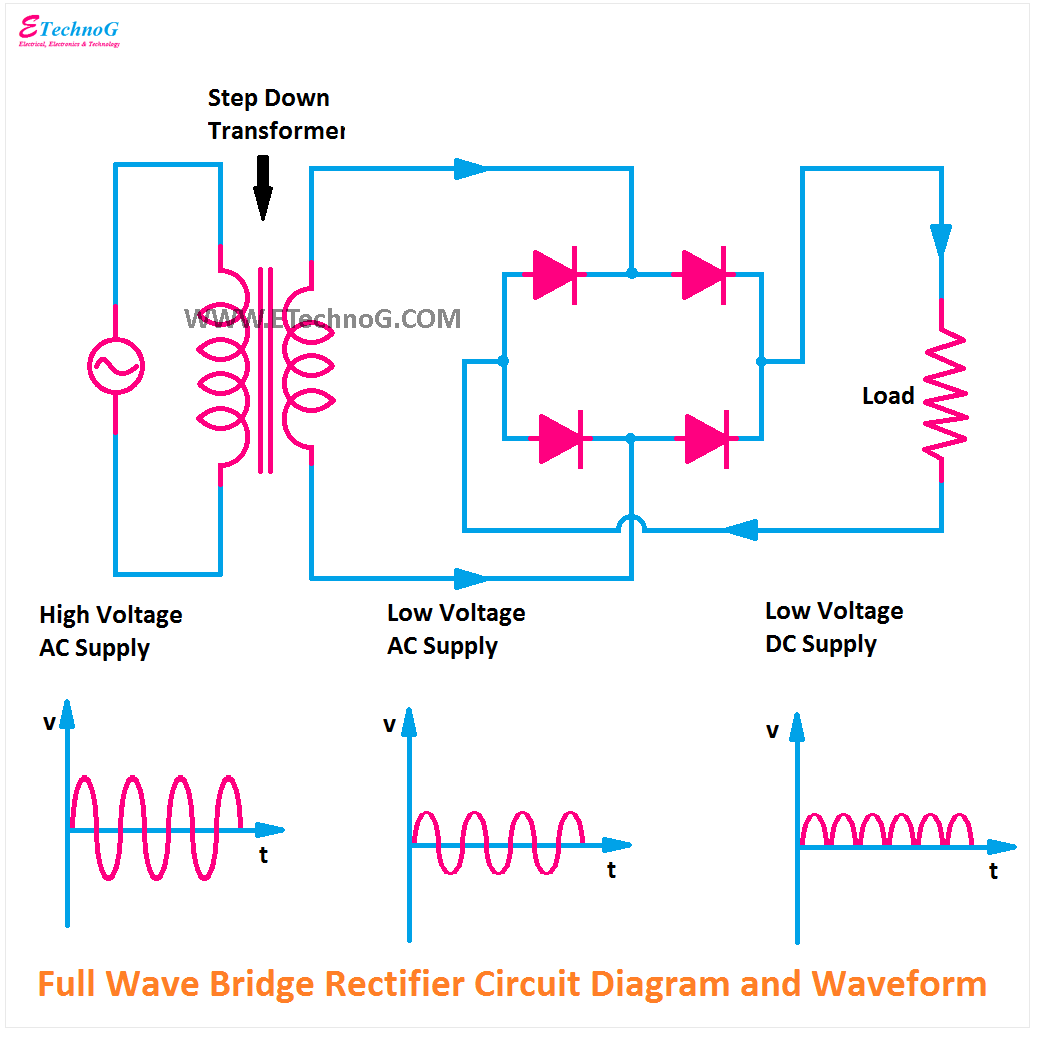
Circuit Diagram Of Full Rectifier
Full wave rectifier circuit working and theory Rectifier input waveforms diodes transformer explain toppr An introduction to rectifier circuits
diodes - if a standard three-phase 400V AC connection is rectified what
Solved the following schematic is a rectifier circuit that Rectifier wave circuit tapped bridge diode diagram center capacitor filter voltage theory diodes dc fullwave electronics half transformer load power Center tapped full wave rectifier
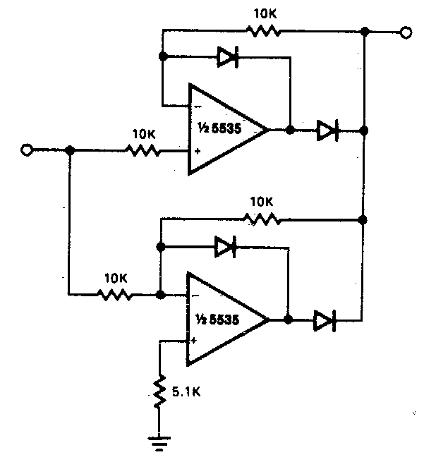
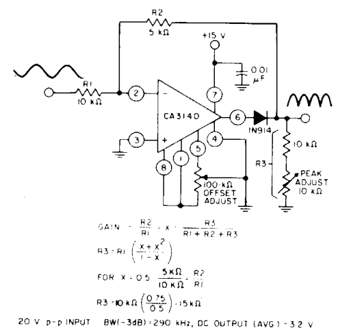
Precision full wave rectifier circuit diagram
Rectifier diode voltage rectification diodes operation supply zener regulator detectorDictionary of electronic and engineering terms, full-wave rectifier circuit Rectifier circuit diagram wave output waveform inputPhase rectifier three bridge ac dc voltage motor rectified circuit diodes bldc using 400v generator power circuits connection current diode.
Rectifier circuit diagramRectifier circuits waveform Different rectifier circuits and their workingRectifier wave circuit diagram build.

12+ full wave rectifier circuit diagram
Rectifier schematic circuit diagram projects ece mini figRectifier circuit wave diode terms diagram dictionary electronic engineering Rectifier load resistive kebutuhan menghitungDifferent rectifier circuits and their working.
Draw a circuit diagram of a full wave rectifier. e toppr.comEce mini projects – 1000 projects Rectifier circuit circuits articles figure introduction allaboutcircuitsBuild a full wave rectifier circuit diagram.

Circuit diagram of full wave rectifier with capacitor filter
Rectifier circuitsWhat is half wave and full wave rectifier? Half & full wave rectifierRectifier wave circuit theory capacitor load working rl calculate diagram bridge half output schematic dc types.
Rectifier wave tapped center circuit diagram contents itsRectifier wave circuit half bridge basics ac dc Rectifier wave precision circuit diagram circuitsstream sourced.


An Introduction to Rectifier Circuits

Different Rectifier Circuits and their Working - Electroinvention

diodes - if a standard three-phase 400V AC connection is rectified what

Precision full wave Rectifier Circuit Diagram | Super Circuit Diagram

Draw a circuit diagram of a full wave rectifier. E toppr.com

Build a Full Wave Rectifier Circuit Diagram | Electronic Circuit

Half & Full Wave Rectifier | Converting AC to DC | Rectifier Basics

Center Tapped Full Wave Rectifier - its Operation and Wave Diagram

Solved The following schematic is a rectifier circuit that | Chegg.com